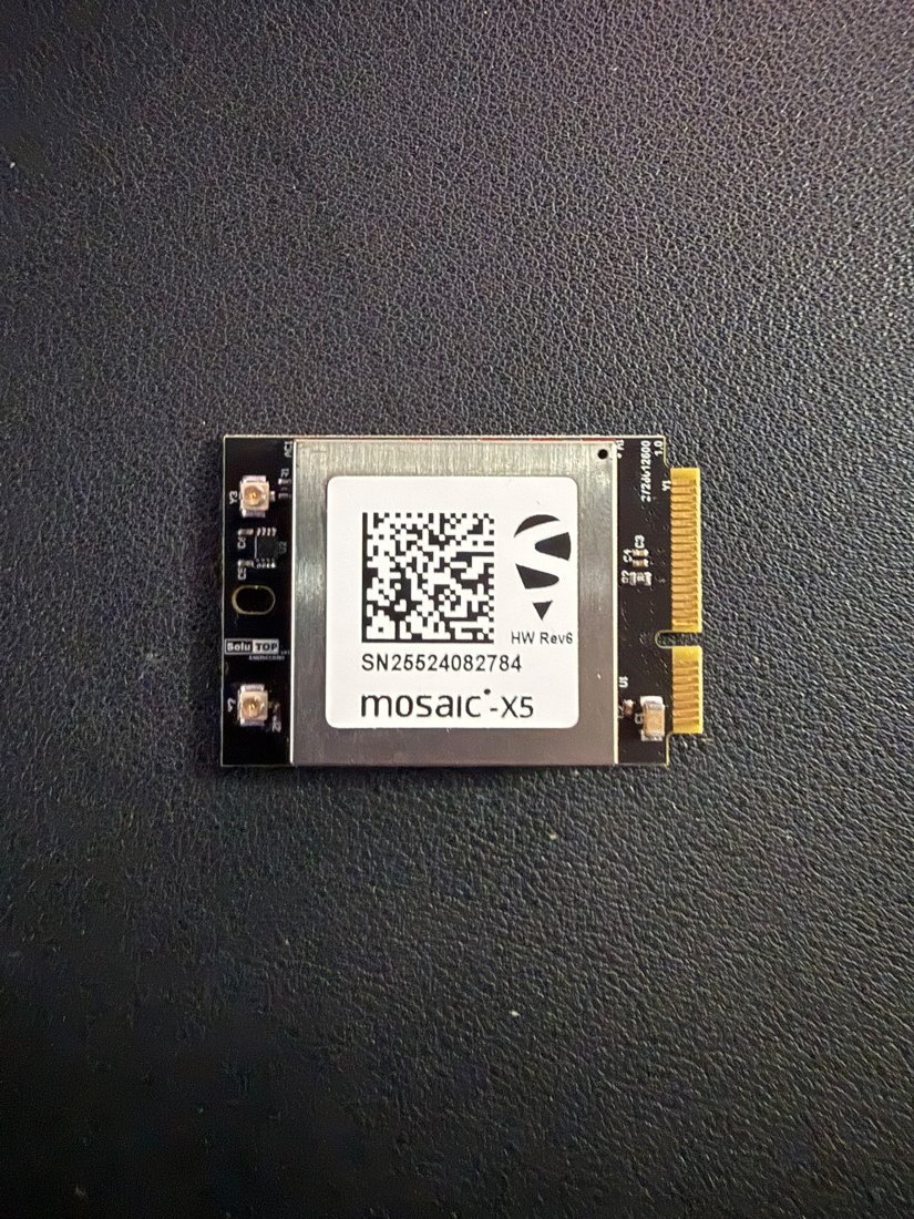
Main
The Main board is the PCB onto which the mosaic-X5 GNSS module is soldered,
together with all the surrounding electronics: power, interfaces, storage and
indicators. The mosaic-X5 module (with QR label, serial number and HW Rev1
marking) is mounted at the centre of the board.
Specifications and dimensions
Main functions:
- housing and powering of the mosaic-X5 module;
- generation of the supply voltages (DC/DC) and protections;
- level shifting and routing of the UARTs;
- USB-C interface to the host;
- microSD slot for raw-data logging;
- status LEDs and LOG button;
- mini-PCIe connector to the Carrier board.
| Characteristic | Value |
|---|---|
| Dimension (measured side) | ≈ 62.8 mm – almost square |
| PCB colour | black (dark solder mask) |
| Mounting holes | 4, at the corners |
| GNSS module | mosaic-X5 soldered at the centre (31 × 31 mm) |
| Hardware revision | HW Rev1 (silkscreened) |
| Serial number | shown on the module label |
| Input voltage | 5 V (USB-C) |
| Module working voltage | 3.3 V (generated on-board) |
| Coupling to the carrier | mini-PCIe connector (see mini-PCIe interface) |
Note
The full dimensions (both sides, thickness, hole spacing) must be taken from the dimensioned mechanical drawing. The designators mentioned come from the SoluTOP board family of the same generation and represent the typical layout. (to be confirmed on the schematic of the production revision)
Functional sections
| Section | Typical components | Notes |
|---|---|---|
| GNSS module | mosaic-X5 (soldered) | RF/GNSS core, SMD-mounted at the centre of the board. |
| Power | DC/DC, ferrites (L1…), PTC fuse (F1) |
3V3 generation, EMI filtering. |
| Serial interfaces | buffer/level shifter (U1, U4) |
Adapt the logic levels of the UARTs. |
| USB | USB-C connector, CC resistors (5k1) | Power + data to the host. |
| Storage | microSD slot (CN1) |
Raw-data logging. |
| Indicators | LEDs, buzzer (U7) |
Receiver status. |
| Control | tactile button (P1) |
LOG / function button. |
Connectors and interfaces
| Ref. | Type | Function |
|---|---|---|
J6 / J8 |
USB Type-C | Host + power (USB data + 5 V) |
J1, J2, J5, J7 |
JST SH 4-way (1 mm) | Serial / auxiliary I/O (UART, PPS) |
J9 / J10 |
JST XH 2-way | Power / battery |
J11 |
Header 2×3 (2.54 mm) | Programming / debug |
J12 |
6-way header (2.54 mm) | General-purpose I/O / testing |
CN1 |
microSD push-pull | Storage (logging) |
Note
Not all connectors are fitted in every configuration. Externally, on the mini carrier, the only interface is USB-C (see Carrier mini).
USB-C — primary interface to the host: 5 V power + the module's USB data line. The CC resistors (5.1 kΩ) set the device as a USB device powered from the cable.
UART (TTL 3.3 V) — the module's serial ports for NMEA-0183 output, SBF output (logging/post-processing) and RTCM 3.x correction input.
Warning
The UART lines are at 3.3 V. Do not connect them to RS-232 signals (±12 V) without a converter: the module would be damaged.
PPS / EVENT — synchronisation pulse (Pulse-Per-Second) and inputs for time-tagging external events, available when provided by the configuration.
Power
USB-C 5V ─► [Fusibile PTC F1] ─► [Filtro EMI/ferriti] ─► [DC/DC] ─► 3V3 ─► mosaic-X5
└─► interfacce / LED
| Item | Ref. | Function |
|---|---|---|
| Input protection | F1 |
Self-resetting PTC fuse 0.75 A. |
| EMI filtering | L1, L2, L4, L5 |
Ferrite bead on the supply lines. |
| DC/DC conversion | regulator | Generates the stable 3.3 V. |
| ESD protection | Schottky / TVS diodes | Transients and reverse polarity. |
mosaic-X5 module consumption: ~ 0.6 W typical; the total depends on the active interfaces.
Tip
Use a USB-C power supply of at least 5 V / 2 A and good-quality cables: long/thin cables cause voltage drops and resets.
LEDs, LOG button and states
The LEDs convey the receiver status at a glance.
Note
The mosaic-X5 module provides two general-purpose LED output pins (max ~10 mA), driven by the firmware. The final number and mapping of the LEDs on the MSX board are to be confirmed in the firmware.
| Colour | Typical meaning | State |
|---|---|---|
| Green | Power | System powered and operational. |
| Bright green | RTK fix | RTK fixed solution (centimetre precision). |
| Yellow | DGPS / float | Differential solution not yet fixed. |
| Blue | Communication | Activity on the data interface. |
| Red | Error / no fix | No solution or error. |
Typical sequence: power-on → steady green LED; satellite search → blinking fix LED; RTK fixed → steady bright-green LED (you can start surveying).
LOG button
The tactile button (P1) is used as a LOG button to start/stop raw-data
recording in the field, without a PC:
- 1st press → starts the logging stream (e.g. SBF at 100 Hz);
- 2nd press → stops the recording and saves the trajectory.
It is the command used for monitoring athletes on the track (see
400m on the track). An optional buzzer (U7) gives
acoustic confirmation of the press and of reaching the RTK fix.
3D model
Interactive 3D model of the Main board (with mosaic-X5 module). It rotates automatically; drag to rotate, scroll to zoom, right-click to pan.
drag rotate · scroll zoom · right-click pan