Carrier mini
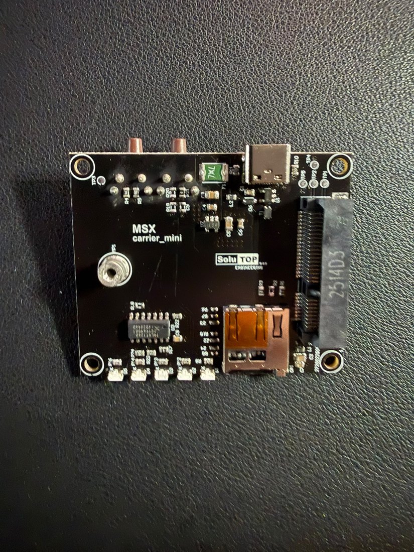
The Carrier mini board (silkscreen MSX carrier_mini / SoluTOP) is the
"motherboard" of the MSX system: it hosts the Main in the
mini-PCIe slot and brings all the I/O to the outside. The GNSS module is
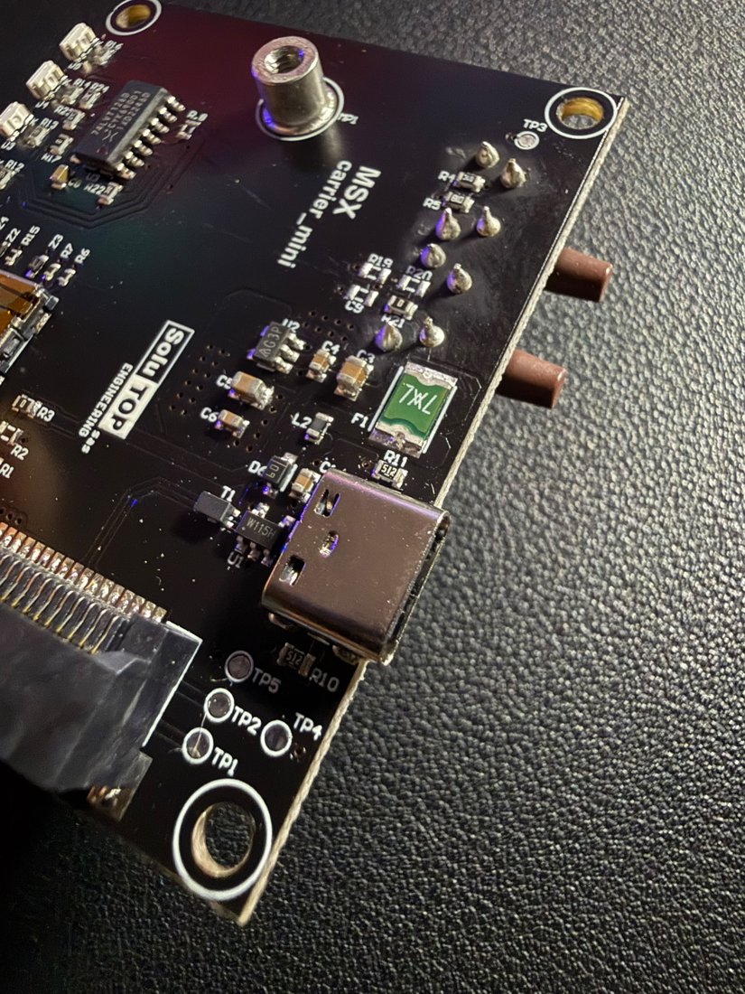
not here: it is on the Main. The carrier carries the USB-C connector, the
microSD slot, the LEDs, the buttons (reset and LOG) and the power
section.
Purpose of the mini carrier
The mini carrier is the simplest, most essential version of the system. Its only purpose is to let you use the receiver entirely over USB. In practice it serves to:
- power the Main from the USB-C port;
- receive the RTK corrections (RTCM 3.x) over USB;
- output the position in NMEA format over USB;
- record the raw-data SBF logs (microSD / over USB).
Info
Externally the only connector is USB-C: no antenna, power or serial ports. On the carrier, however, there are on-board the microSD slot, the LEDs and the buttons. Future carriers (e.g. Ethernet for electrical cabinets, UART, external antenna) are made by changing only the carrier, reusing the same Main through the mini-PCIe interface.
The full operating flow is in USB operation; raw-data logging in Raw data.
Role in the system
- Mechanical support: hosts and secures the Main through the mini-PCIe slot and the holes/standoffs, defining the overall footprint.
- Power: from the USB-C 5 V it generates the voltages for the module.
- I/O: exposes the USB-C to the host, hosts the microSD, the status LEDs and the buttons, and routes the signals to the Main through the mPCIe slot.
Note
The GNSS antenna connector is not on the carrier: the antenna connects on the Main / mosaic-X5 module. (RF connector type to be confirmed)
Why a separate board
Separating the carrier from the card carrying the module makes it possible to:
- mount the same GNSS module on carriers with different features;
- add external interfaces (Ethernet, UART, etc.) in the future without redesigning the RF/GNSS part;
- simplify servicing and replacement.
Coupling is via the mini-PCIe (mPCIe) slot: see mini-PCIe interface.
Connectors
| Connector | Type | Function |
|---|---|---|
| USB-C | USB Type-C | The only external connector: 5 V power + USB data to the host. The CC resistors (5.1 kΩ) set the device powered from the cable. |
microSD (CN1) |
push-pull slot | Storage for raw-data logging. |
| mini-PCIe slot | mPCIe connector | Receives the Main (see mini-PCIe interface). |
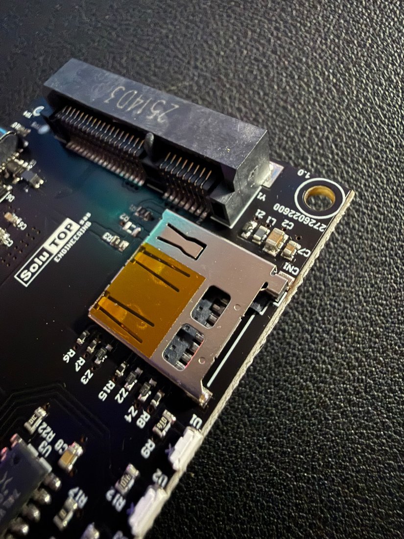
Insert the microSD before powering on
The disk is detected only at start-up: insert the microSD before powering the system. Only then, at power-on, does the microSD green LED turn steady, confirming the disk is mounted and ready for logging. The green LED then blinks during recording (LOG button). If the SD is inserted while already powered, the LED stays off → power off and on again.
Power
From the USB-C 5 V the carrier generates the 3.3 V for the module:
USB-C 5V ─► [PTC fuse F1] ─► [EMI filter/ferrites] ─► [DC/DC] ─► 3V3 ─► (mPCIe) ─► mosaic-X5
                                                            └─► carrier LEDs / logic
| Item | Ref. | Function |
|---|---|---|
| Input protection | F1 |
Self-resetting PTC fuse 0.75 A. |
| EMI filtering | ferrites (L1, L2…) |
Beads on the supply lines. |
| DC/DC conversion | regulator | Generates the stable 3.3 V. |
| ESD protection | Schottky / TVS diodes | Transients and reverse polarity. |
Tip
Use a USB-C power supply of at least 5 V / 2 A and good-quality cables: long/thin cables cause voltage drops and resets.
LEDs and states
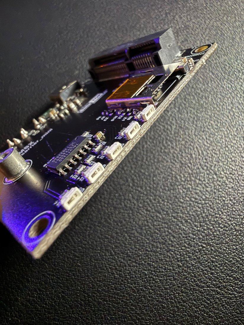
The LEDs on the carrier convey the receiver status at a glance. They are driven by the mosaic-X5 module firmware (LED outputs) and by the on-board logic.
| Colour | Typical meaning | State |
|---|---|---|
| Green | Power | System powered and operational. |
| Bright green | RTK fix | RTK fixed solution (centimetre precision). |
| Yellow | DGPS / float | Differential solution not yet fixed. |
| Blue | Communication | Activity on the data interface. |
| Red | Error / no fix | No solution or error. |
Typical sequence: power-on → steady green LED; satellite search → blinking fix LED; RTK fixed → steady bright-green LED (you can start surveying).
Note
The final number and mapping of the LEDs are to be confirmed in the MSX firmware.
Buttons: reset and LOG
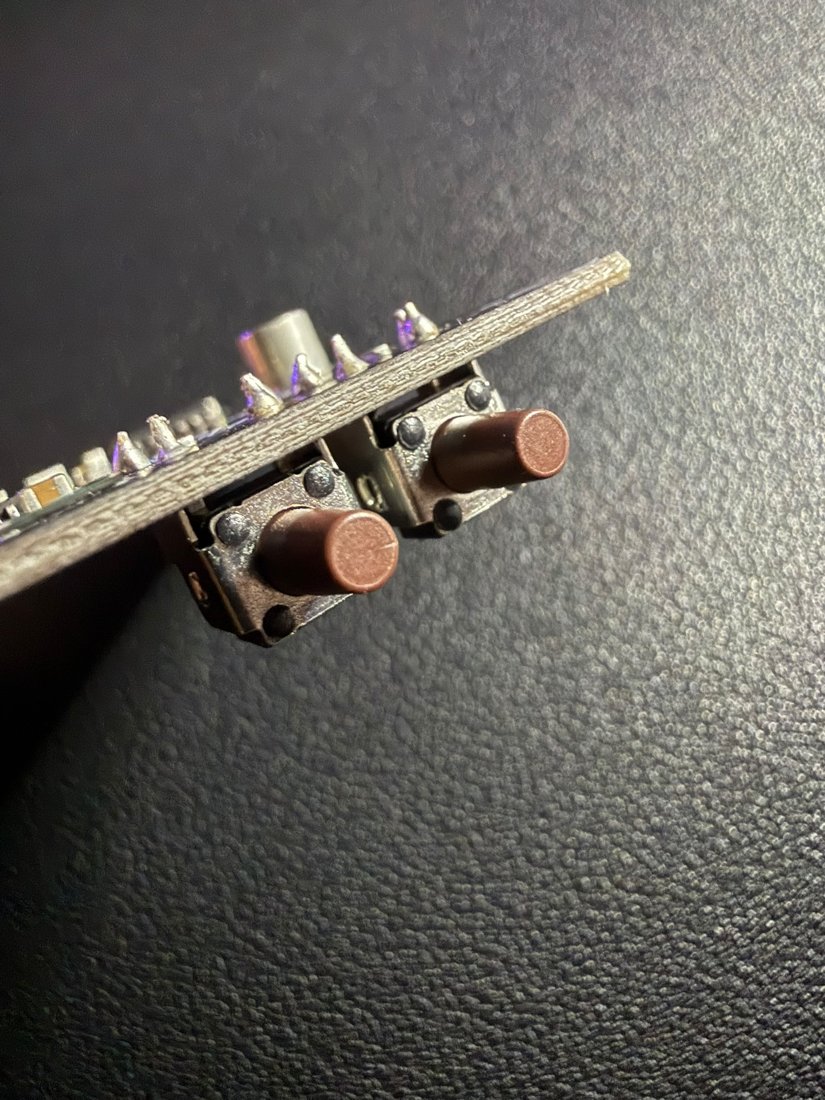
The carrier has two tactile buttons side by side. To tell them apart:
- Reset — the button nearer the USB-C / microSD edge. Restarts the receiver (equivalent to a power-cycle of the module).
-
LOG — the outermost button (away from the USB-C). Starts/stops raw-data recording in the field, without a PC:
- 1st press → starts the logging stream (e.g. SBF at 100 Hz); the green LED goes from steady to blinking;
- 2nd press → stops the recording and saves the trajectory (the green LED goes back steady).
It is the command used for monitoring athletes on the track (see 400m on the track). An optional buzzer gives acoustic confirmation.
Mechanics
| Characteristic | Value |
|---|---|
| Type | Carrier / backplane for GNSS module |
| Coupling | mini-PCIe (mPCIe) slot + mounting holes/standoffs |
| External connector | USB-C only |
| Footprint | ≈ 62.8 mm per side (see 3D model) (dimensions from the mechanical drawing) |
Note
The exact dimensions (thickness, hole spacing) are defined in the carrier's mechanical drawing; the 3D model allows indicative measurements.
3D model
Interactive 3D model of the Carrier mini board. It rotates automatically; drag to rotate, scroll to zoom, right-click to pan.
drag rotate · scroll zoom · right-click pan