Assembly
This page describes how the Main and Carrier boards mate.
Assembly sequence
- Preparation (with the system powered off): make sure the Main's mini-PCIe connector and the carrier slot are clean and undamaged.
- Insertion: present the Main to the mini-PCIe slot at ~45°, aligning the polarisation key, and push it fully in.
- Latching: lower the board until the side clips snap into place.
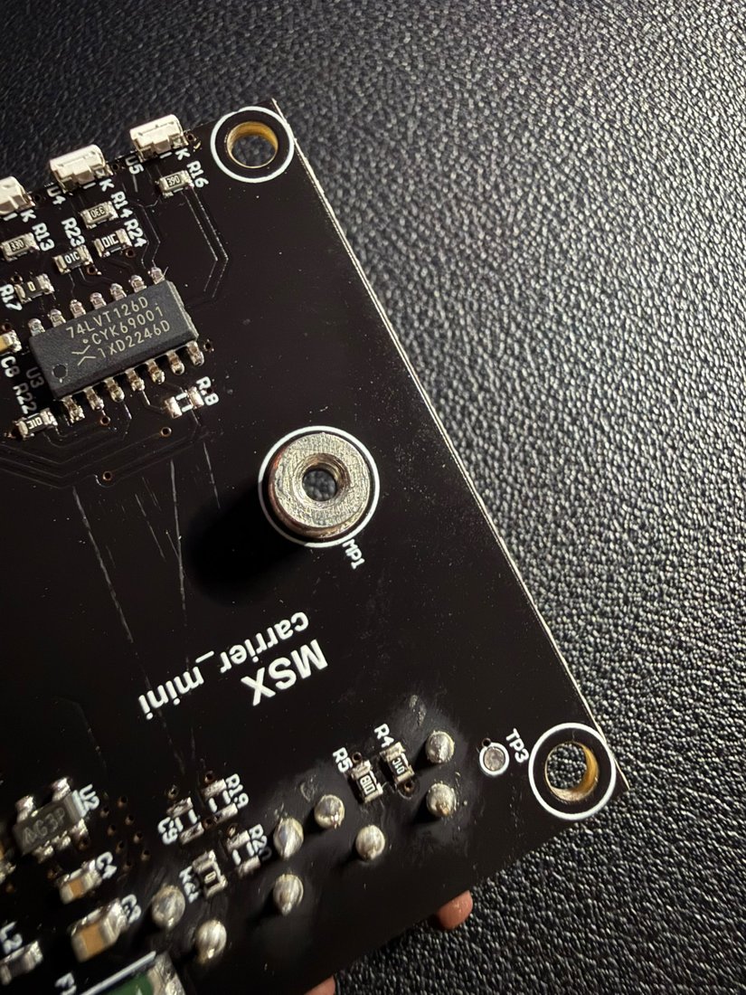
- Fastening: screw the standoff/screws into the mounting holes.
- Antenna: connect the active GNSS antenna to the RF connector on the Main board (not on the carrier).
- Host: connect the USB-C cable to the carrier.
Warning
Do not insert/remove the Main while the system is powered: always disconnect USB before working on the coupling.
Checks after assembly
- At power-on the power LED (green) lights up steadily.
- When the host is connected via USB-C, the device is recognised.
- With the antenna under open sky, acquisition starts within a few seconds (fix LED blinking → steady).
The 3D model of the complete assembly is on the Home page.